
TM 5-1260-206-12
Table 2-2.
APPS Assembly Procedures - Continued
STEP
ITEM
NO.
PROCEDURE
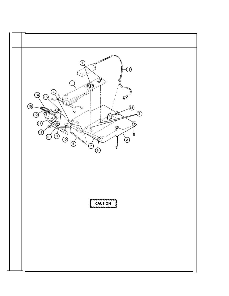
U s e this illustration
for steps 10 through
16
10
Measuring mark bridge (1) - Remove from case 4.
a.
Set measuring mark bridge on top of base plate (2).
b.
Align locator pins with holes in base plate (3).
c.
Tighten two knurled screws (4).
1
Right large mirror assembly (5) - Remove from case 5.
Left large mirror assembly (6) - Remove from case 5.
Do not touch mirrors, lenses, or prisms with fingers.
Do not place any of these components face down on
any surface.
a.
Insert right mirror tube (with 1 red dot on end) (7) into hole
on right side of base plate (8). Align dots and push to seat
tube.
Insert and seat remaining mirror tube into hole on left side of
b.
base plate. Align two red dots and push to seat.
2-28

 Previous Page
