
TM 11-5826-225-35
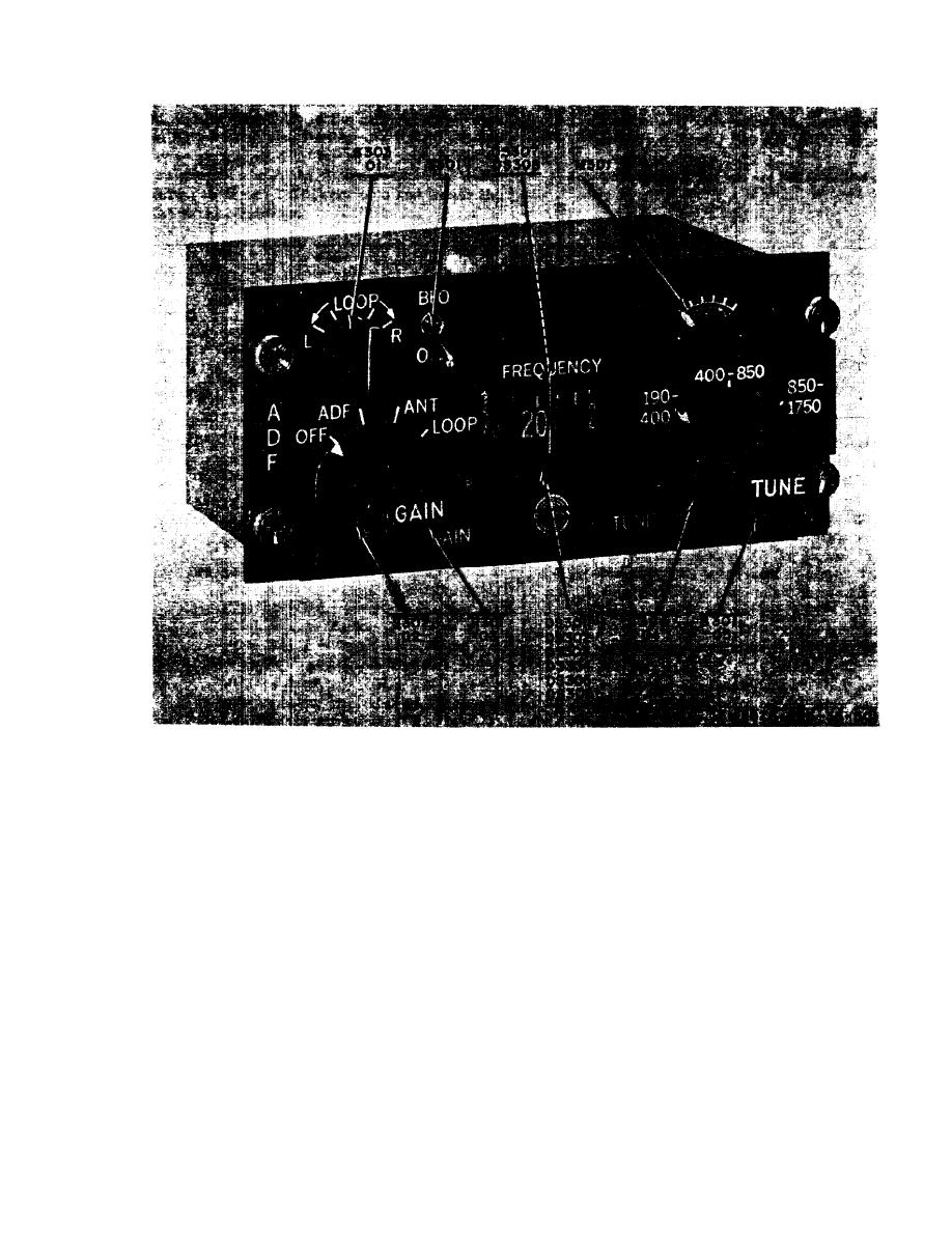
Figure 220. Control unit, front view.
(8) Set CONTROL TEST switch to po-
should read zero ohms. A reading
s i t i o n 4. Turn control unit GAIN
other than zero ohms indicates that
control fully counterclockwise. With
function switch wafer S302-A is not
the function switch in either ADF or
making contact.
ANT position, the multimeter should
(7) S e t function switch to ANT and
read 5,000 ohms which is the resist-
L O O P positions. The multimeter
ance of variable resistor R301C.
should indicate from 5,000 ohms to
(9) Set function switch to LOOP. A mul-
zero ohms as the GAIN control is
timeter reading much different than
turned clockwise. A multimeter read-
5,470 ohms indicates that resistor
ing other than the above indicates
R303 in series with R301C is de-
e i t h e r that function switch wafer
fective.
S302-A or RF gain variable resis-
( l o ) Set CONTROL TEST switch to posi-
tor R301-C is defective.
2-37

 Previous Page
