
TM 11-6625-821-45
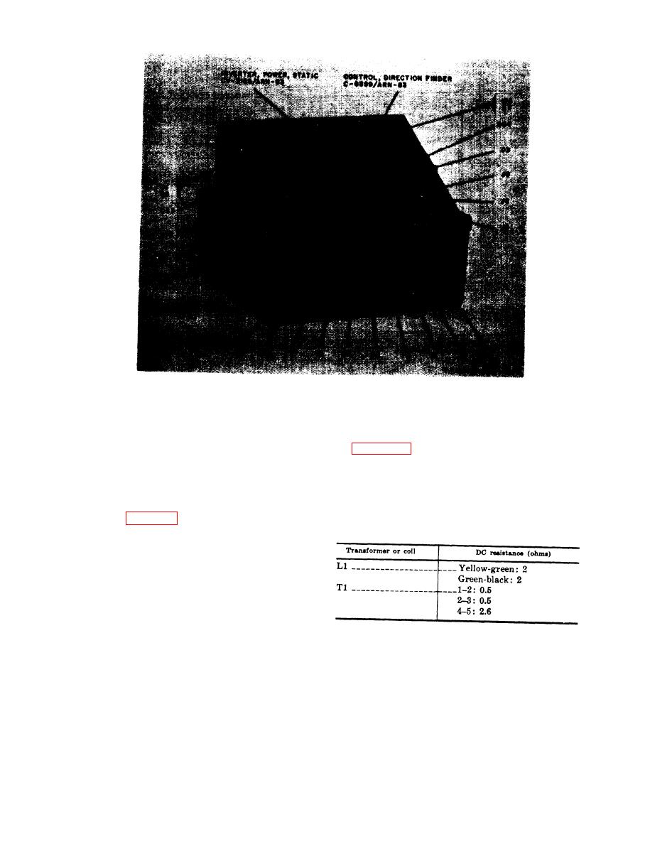
Figure 2-1. Test unit, front panel.
to make the voltage measurement illustrated
If the trouble has been traced to the inverter,
in figure 2-8. Refer also to the dc resistances
localize the trouble by voltage measurements.
of transformed and coils (e below).
a. Equipment Setup. Set the test set DC
d. Adjustment. After the trouble has been
POWER switch to OFF, and set UP the equip-
localized and repaired, refer to TM 11-5826-
ment as follows:
225-35 to adjust the inverter.
(1) Remove the inverter from the test set
e. Dc Resistances of Transformers and Coils
in Inverter.
(2) Connect one end of cable W4 to con-
nector J6 in the test set.
(3) Connect the other end of cable W4 to
the connector on the inverter.
(4) Connect the test set to a 27.5-volt dc
power sours.
b. Switch Positions. Set the switches on the
test set as follows:
(1) RECEIVER-CONTROL to CON-
TROL,
Simulator Circuit -
(2) DC POWER to ON.
If the trouble has been traced to the loop
(3) All other switches may be set to any
antenna simulator circuit, localize the trouble
position.
as follows:

 Previous Page
