
TM 11-6625-821-45
b. Switch and Control Positions.
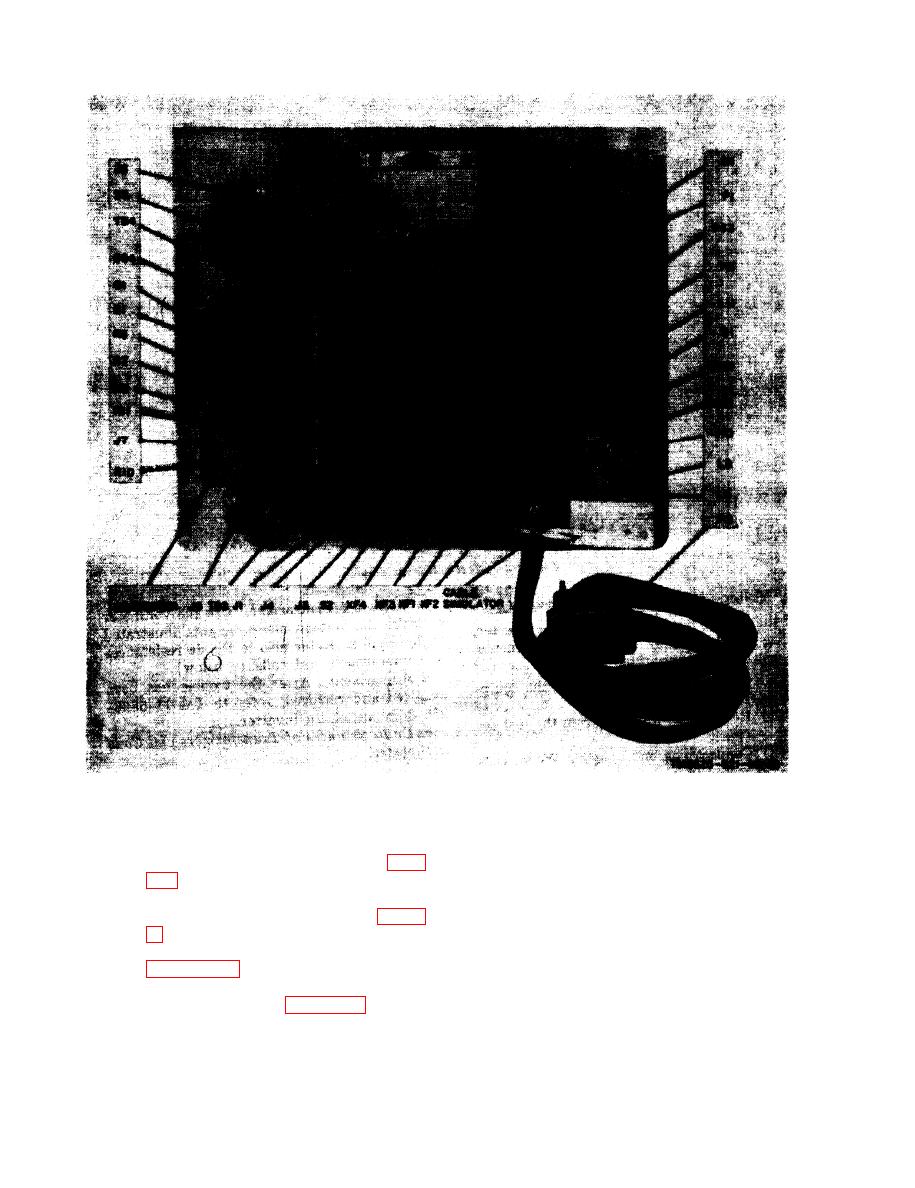
a. Equipment Setup.
(1) Remove the test set front panel (para
(1) Adjust the LOOP SIMULATOR on
the test set so the needle points to N
(2) Remove the covers from the converter
(0). (All other switches on the test
and cable simulator circuits (fig. 2
set may be set to any position.)
(2) Adjust the signal generator as fol-
(3) Connect the equipment as shown in
lows:
the test jig used in the equipment set-
(a) Set the RANGE selector to 530-
up is illustrated in figure 4-3.
1800 kc.
2-6


 Previous Page
