the same direction and phase as the magnetic field
b. Tuning Meter and Tuning Control Informa-
set up by the rotor in the tuning synchro. Since the
tion (fig. 5-6). Control unit tuning control informa-
rotor in the BEARING INDICATOR synchro fol-
tion is indicated on BEARING INDICATOR DS3
lows this magnetic field, the BEARING INDI-
A control unit synchro transmitter (tuning syn-
CATOR will follow any rotation of the tuning syn-
chro B301) produces the tuning control informa-
chro rotor. The test set supplies the control unit
tion, and synchro receiver B2 in the BEARING
tuning meter with a current that deflects the nee-
INDICATOR receives the information. When the
dle to midscale. The test set power circuit applies
control unit function switch is in any position
27.5 volts dc to resistor R9, which limits the cur-
other than OFF, rear switch wafer S302B con-
rent to approximately 50 microampere.
nects 26 volts, 400 cps from the power circuit in the
RECEIVER-CONTROL switch S4 connects the
test set to the rotors of the tuning synchro and
current to the control unit tuning meter. The test
rotors of the synchro receiver in the BEARING
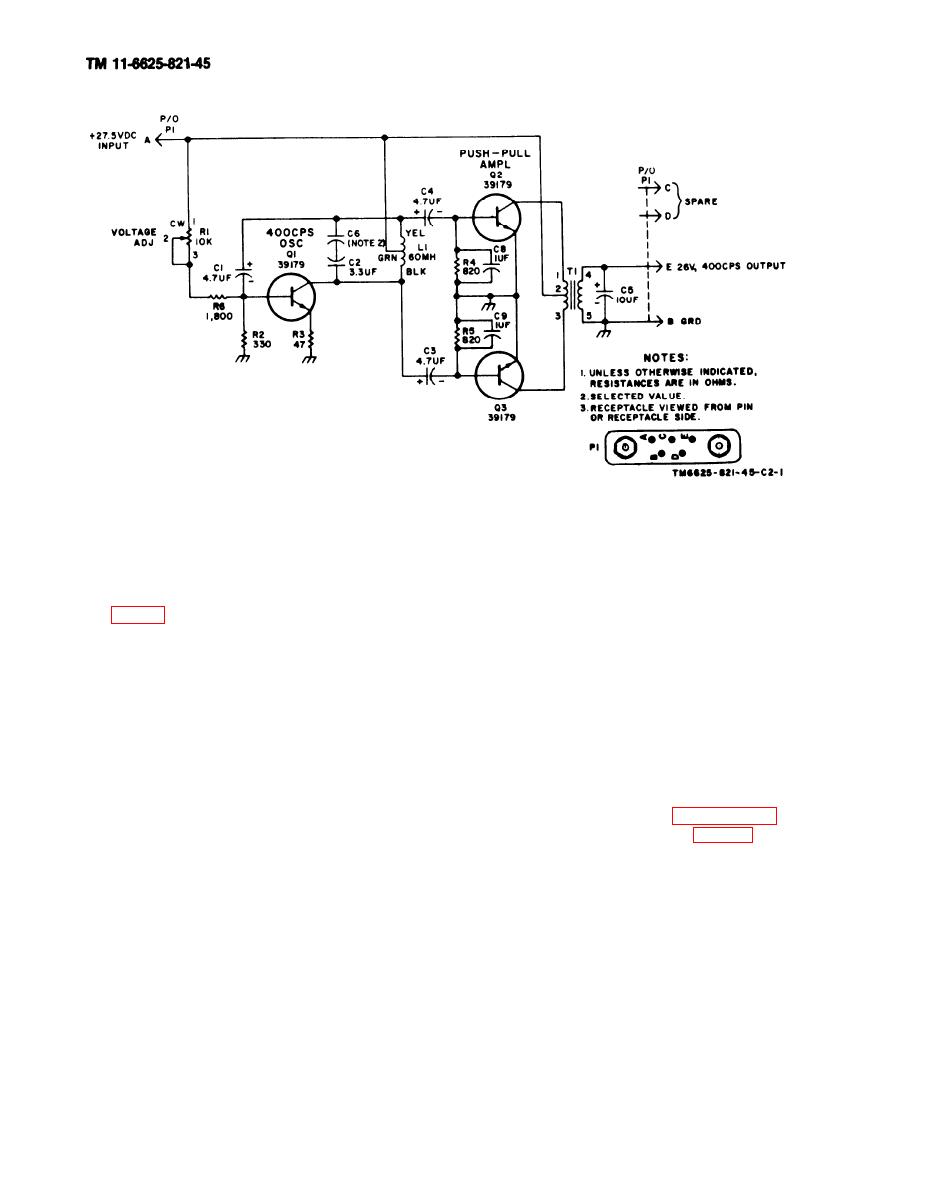
set power circuit is described in paragraph 1-4.
INDICATOR. The rotor in the tuning synchro
c. Manual LOOP Control Circuit (fig. 5-7). The
induces a voltage into its stator windings.
test set provides a resistance check for the manual
RECEIVER-CONTROL switch S4 connects these
LOOP control circuit in the control unit. When set
voltages to the stators in the BEARING INDI-
to position 1, CONTROL TEST switch S3 con-
CATOR synchro. A magnetic field is then setup in
nects CONTROL TEST terminal J3 to common
the BEARING INDICATOR synchro that has
Change 2


 Previous Page
