
TM 11-5826-225-25
(6) Rotate the test set LOOP SIMULA-
TOR dial clockwise as required for
for 5 volts dc on vtvm. Divide signal
an indication of 20 millivolts ac on
level recorded in (2) above by the
the vtvm. If necessary, increase the
present output of signal generator.
signal generator output signal.
The gain at 200 kc should be approxi-
mately 0.008.
(7) Turn variable resistor R131 (fig. 2-8)
(5) Repeat (1) through (4) above for the
fully clockwise.
remaining frequencies listed in the
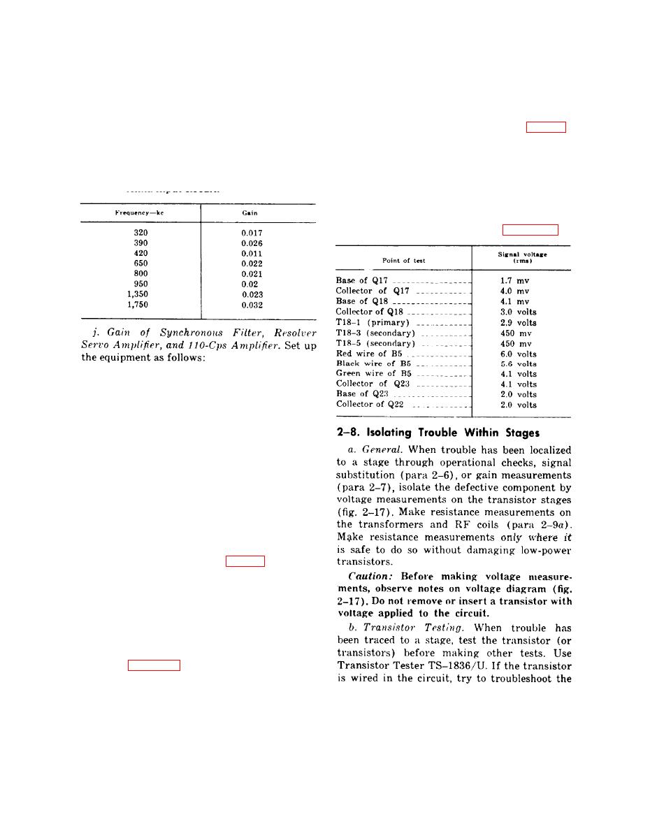
(8) Using vtvm, measure the signal volt-
following chart. If gain differs ap-
ages at the points indicated in the
preciably, check resolver and loop an-
following chart. If a voltage is ap-
tenna input circuit.
preciably less than indicated, check
transistors and associated circuit com-
p o n e n t s . After these tests, adjust
variable resistor R131 ( para 320).
(1) Set control unit function switch to
ANT, BFOOFF switch to BFO, range
switch to 190- to 400-kc range, and
GAIN control fully clockwise. Tune
to 300 kc.
Adjust signal generator controls for
(2)
a 300-kc output signal at a level of
50 microvolt. Connect signal gener-
ator output to test set input.
Tune control unit for zero beat in
(3)
headset, then set BFO-OFF switch
to OFF. Set function switch to ADF.
Set vtvm to ac measuring range and
(4)
connect probe to the emitter of first
agc amplifier Q16 (fig. 23).
Set GONIO DRIVE switch to ON.
(5)
When the test set BEARING INDI-
CATOR and LOOP SIMULATOR
dials have the same indication,, lock
the shaft of resolver servo motor B5.
Lock the shaft by stretching a rubber
hand around the large gear shown in
ceiver chassis.
2-29

 Previous Page
