TM 11-5826-225-35
Gain of First RF Amplifier and Phase-
ciably from that listed in the chart,
h.
Shift Network.
check the alignment of sense antenna
input circuit. After these tests, adjust
(1) Repeat e (1) through (7).
R90 (para 3-17).
(2) Using 50-ohm probe, apply signal gen-
erator output to the base of Q3 (fig.
2-8). Adjust output signal for a 5-
volt dc indication on the vtvm. Re-
cord output signal of signal genera-
tor.
(3) Using 50-ohm probe, connect signal
generator to the base of Q1 (fig. 28).
Adjust output signal for a reading of
5 volts dc on vtvm.
(`4) Divide value recorded in (2) above
by the value obtained in (3) above,
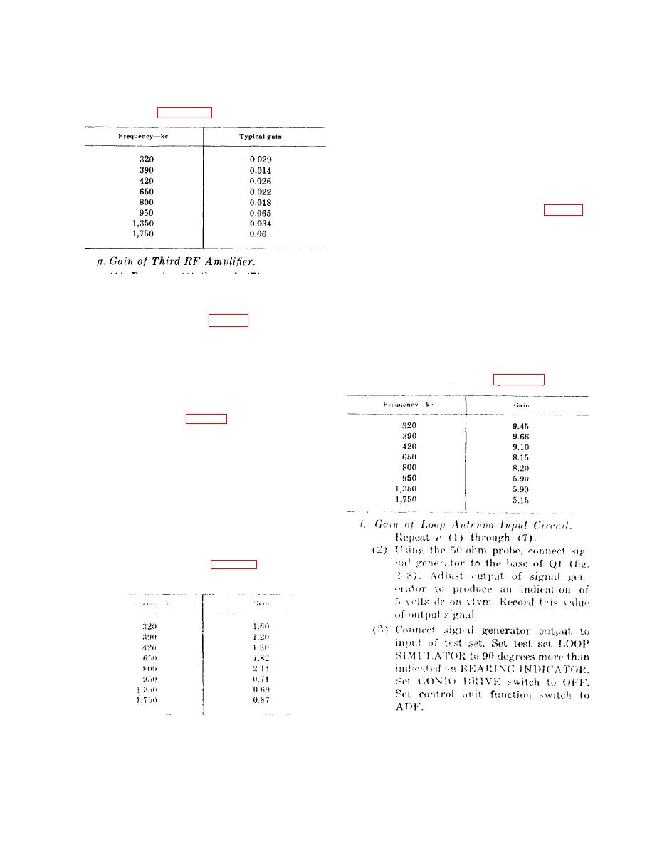
(1) Repeat e (1) through (7).
At a frequency of 200 kc, a typical
gain figure is 4.6. Repeat (1) through
(2) Listing 50-ohm probe, apply signal
(3) above for the remaining frequen-
generator output signal to the base of
cies listed in the following chart. If
transistor Q4 (fig. 28).
gain figures differ appreciably, check
(3) Adjust output of signal generator for
transistor Q1 and associated circuit
an indication of 5 volts dc on vtvm.
components. If necessary, use further
Record the signal generator required
isolating techniques to locate the de-
for this dc voltage level.
fective component (para 2-8).
(4) Using 50-ohm probe, connect signal
generator output to the base of tran-
sistor Q3 (fig. 28). Adjust output of
signal generator to obtain 5 volts dc
on vtvm.
Divide the signal generator output
(5)
signal determined in (3) above by the
value obtained in (4) shove, A typical
g a i n value for a freqency of 200 k c
is 0.73. Repeat (1) through (4) above
at the frequencies listed in the chart
(1)
below. If gain differs appreciably than
listed in the chart, use further isolat-
ing techniques (para 2-8) to deter-
mine the trouble.
2-28


 Previous Page
