
Section VII
alignment of Monitor telescope as follows:
Readout error is defined as the difference
a. Mount magnetic azimuth reference detector of
between Monitor, Turntable, or HEADING
field tester on Turntable, in a magnetically stable
SELECTOR heading and the heading indi-
area, using mounting screws provided, and accurately
cated by readout of Console when at null.
level the Turntable. With telescope upright, tighten
Positive errors appear on white scale of
mounting screws on magnetic azimuth reference
MINUTES window and negative errors on red
detector.
scale.
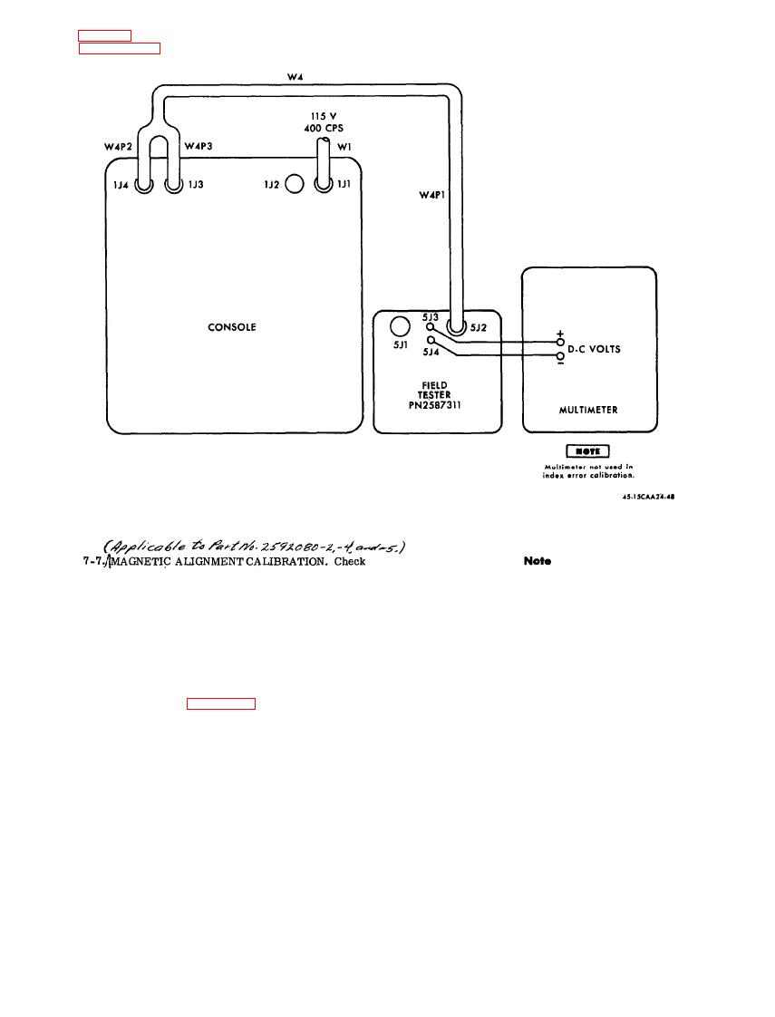
b. Connect cable assembly W2 to 1J3 connector of
Console and magnetic azimuth reference detector P3
d. Rotate Turntable to 90-, 180-, and 270-degree
to Turntable. See figure 7-2. Set up Console as
headings. Record error at each heading.
follows :
E 1, E2 switches to OFF.
e. Add the errors at the four headings (0, 90, 180,
MODE SELECTOR to MON.
270 degrees) algebraically and divide by four. This
POWER ON-OFF to POWER ON.
is the index error (11). Record this value.
VOLTS ADJUST to 23.5 on EXC VOLTS meter.
READOUT SELECT to FV .
f. Sight a target at a distance of at least 1/2 mile,
c. Rotate Turntable to obtain 0 10 minutes on
using the magnetic azimuth reference detector tele -
readout and set azimuth scale to 0. Record readout
scope. Target elevation shall be within 5 degrees
error.
of horizontal. Record the bearing (B) of this target.
7-8

 Previous Page
