
TM5-1260-206-34
Table 2-10.
APPS System Fine Alignment Procedures - Continued
STEP ITEM
NO.
PROCEDURE
25
Adjust screw (14)
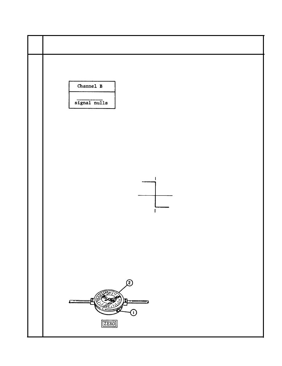
Observe that channel B sine wave nulls as adjust screw is rotated.
Rotate adjust screw until the following is observed:
26
a. Set as follows:
Display Mode = Channel A
TIME/DIV
= 10 usec/cm
MAGNIFIER
=X10
b.
Rotate HORIZONTAL POSITION control until the high-to-low
transition is on the center grid line of the oscilloscope.
NOTE
The square wave transition is used as
a zero reference point. As the photo-
carriage is moved the reference point
will move.
27
System zero
Zero alignment meter (15) by doing the following:
a.
1.
Loosen locking screw (l).
2.
Rotate dial (2) to indicate
zero.
3.
Tighten locking screw.
b.
Press:
2-45


 Previous Page
