
TM5-1260-206-34
Table 2-10.
APPS System Fine Alignment Procedures - Continued
STEP
ITEM
NO.
PROCEDURE
19
Guide bar (3)
Insure clamp (6) is in middle position.
a.
Pull spring loaded block (2) to accommodate guide bar. Place
b.
guide bar in block to contact three rollers. Position clamps
(6 and 7) on back and front edges of base plate. Do not
tighten clamps.
20
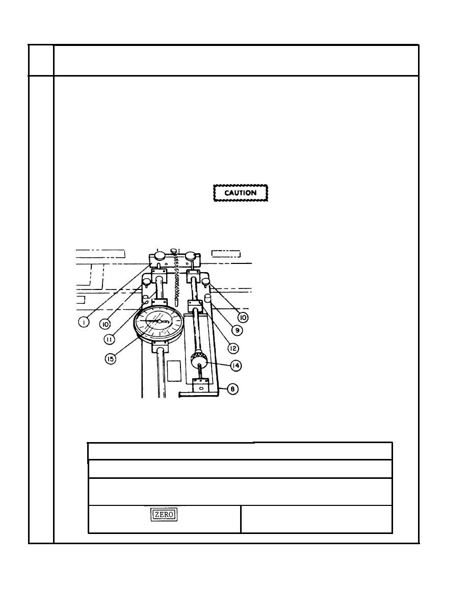
Precision alignment assembly (8)
The precision alignment assembly is a
delicate instrument. Handle with care.
Install by doing the following:
a.
Insert assembly clamps (9)
into slots on front of base
plate. Tighten clamp
screws (10).
b.
Move photo-carriage until
meter-rod (11) and push
rod (12) align with bar (l).
Tighten guide for clamps
(6) and (7).
21
Guide bar (3)
Align by doing the following:
Digital Display Indication
Action
I
a. Apply power to APPS.
Keep slight pressure against
Move photo-carriage to front.
b.
guide bar.
x
x
PRESS :
c.
0.000
0.000
2-42


 Previous Page
