TM 5-6675-250-10
2-1. OPERATOR'S CONTROLS AND INDICATORS - Continued
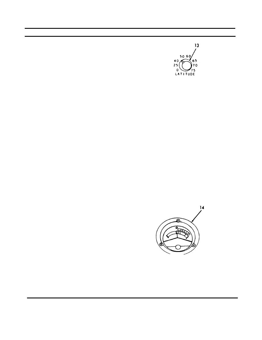
(13) Latitude select switch (13). The LATl-
TUDE select switch is provided to
maintain instrument operating time
at different latitudes of operation.
T h e switch is adjustable with a
screwdriver and contains eight posi-
tions. The switch positions and corre-
sponding latitudes of operation are
as follows:
Latitude of Operation
Switch Position
0-15 degrees
0
15-30 degrees
25
30-45 degrees
40
45-55 degrees
50
55-63 degrees
60
63-67 degrees
65
67-73 degrees
70
73-75 degrees
75
(14) Test meter (14). The TEST METER
provides a visual indication of opera-
t i o n a l status of the instrument in
both testing and operating modes.
Satisfactory operation of the circuits
associated with TEST SELECT switch
position is indicated by the meter
pointer. The meter and the TEST
SELECT switch are used in conjunc-
tion with the PRESS TO TEST switch,
which must be actuated to obtain
m e t e r indications during self-test
operation. When the TEST SELECT
switch is in the SOURCE VOLTAGE
position, the input voltage may be
read on the voltage scale on the right
side of the meter scale. When the
TEST SELECT switch is in the GYRO
position, the meter pointer should
center in the yellow area. When the
TEST SELECT switch is in any other
position, the meter pointer should be
in the green area.
2-16


 Previous Page
