
TM 11-4920-292-15
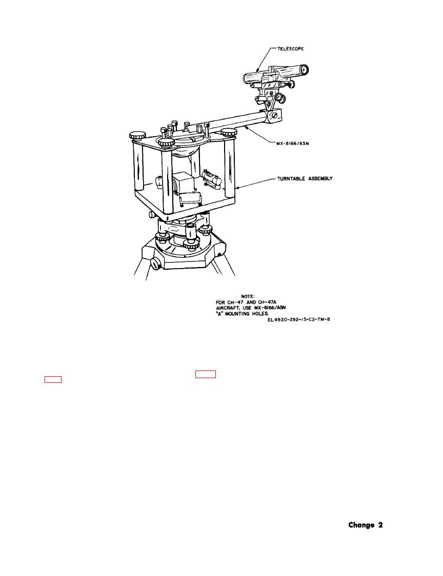
in CH-47 and CH-47A aircraft.
NOTE
(6) Determine aircraft misalignment
Clockwise rotation of the drum dial
(minutes) from nomograph shown in figure
corresponds with increasing heading.
One turn of the dial is equivalent to
swing data sheet. Polarity is same as on line
1 of correction, Each dial division is
E-4 of the swing data sheet.
equal to 1 minute. If E-6 is positive,
(7) Determine optical alignment correc-
rotate the fine azimuth adjustment
tion from the equation given in section E of the
clockwise for upright optics and coun-
swing data sheet and record on line E-6 of
terclockwise for inverted optics.
the swing data sheet.
(10) Tighten the telescope fine adjust-
(8) Loosen the telescope fine adjustment
ment clamp,
clamp.
(9) Rotate the telescope fine azimuth ad-
aircraft as follows:
justment screw by an amount equal to optical
(1) Remove the compass transmitter with
alignment correction of line E-6 of the swing
the optical transfer equipment attached from
data sheet.
the turntable assembly.
9-13

 Previous Page
