
TM 11-4920-292-15
the TRANSMISSION control until the heading
indicated on the digital controller decreases
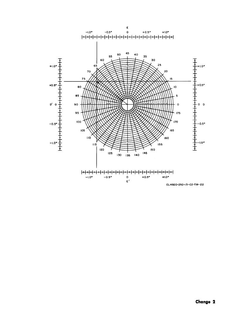
error is the length of the line from the center
by the magnitude of the transmission error
of the figure to the intersection point and is read
( (4) (e) above). Tighten the center locking nut
on the concentric ring scale.
on the TRANSMISSION control.
(f) The direction of the transmission
(6) Update the control console voltages
error is determined by the intersection of the
for magnetic field changes. If the compensation
line with the polar scale.
procedure required more than 45 minutes, re-
(5) Remove transmission error as follows:
peat the procedures given in (2) above.
(a) Set the remote magnetic compen-
(7) Perform 24-heading electrical swing
sator TRANSMISSION outer control knob to
as follows:
the direction of the transmission error and
(a) Set the control console switches as
tighten the locking screw.
follows :
(b) Set the HEADING SELECTOR
1. MODE SELECTOR: IND.
switch to the heading division nearest the di-
2. READOUT SELECT: 0.
rection of the transmission error.
(b) Set the HEADING SELECTOR
(c) Rotate the center slotted shaft of
switch in 15 increments. Record errors as in-
9-27


 Previous Page
