Home
Download PDF
Order CD-ROM
Order in Print
Home
>
Directional Meter Maintenance and Training Manuals
>
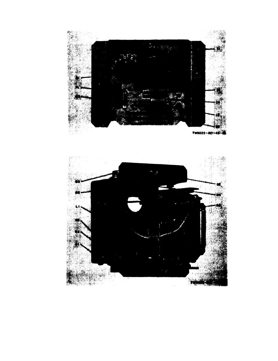
> Figure 2-10. Inverter, bottom view with bracket removed.
Figure 2-8. Inverter voltage diagram.
Figure 2-11. Loop antenna simulator circuit voltage diagram, with LOOP SIMULATOR set to OO.
TM-11-6625-821-45 Test Set Direction Finder Set AN/ARM-93 Manual
Page Navigation
17
18
19
20
21
22
23
24
25
26
27
TM
11-6625-821-45
Figure
2-9.
Inverter,
bottom
view.
Figure
2-10.
Inverter,
bottom
view
with
bracket removed.
2-11


 Previous Page
