
TM 11-6605-202-12/TO 5N3-3-10-1
REPLACEMENT OF THE GYRO (continued)
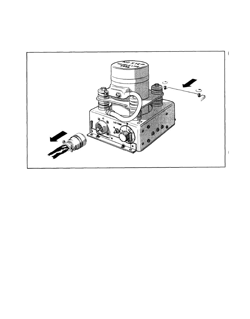
4-16. Removal (continued)
4-17. Replacement
Make sure that the power is not applied to the compass set.
Loosen back screws by turning counterclockwise.
Set gyro assembly on mounting plate, slide gyro away from you, toward rear mounting screws, till
q
the two notches on the rear mounting flange engage the two screws. DO NOT TIGHTEN SCREWS.
Line up the two front holes in the gyro front mounting flange with the holes in the mounting plate.
Insert screws and tighten.
Tighten rear mounting screws.
Connect the aircraft mating connector to J1 on the base of the gyro assembly.
4-16

 Previous Page
