
t u r n i n g o ftit h e a d j u s t e r w i t h a s c r e w d r i v e r
States
the
azimuth
scale
approximately
1,800 mils. The scale is read against a
fixed index under t the rear sight hinge .
e. Front and Rear Sight Assemblies.
( 1 ) The
front sight (fig. 5) is hinged to
a bracket on the cover of the com-
pass and folds against the top sur-
face of the cover.
(2) The rear sight (fig. 6) is hinged tc
a rear sight holder which in turn
is hinged to a bracket. The bracket
is secured to the body of the com-
pass so as to permit folding the
sight against the window inside the
cover when the instrument is not
in use.
5. Characteristics
Figure 2. Compass M2.
Angle
of
site
scale
.
.
.
.
.
.
.
1,200-0-1,200
roils
Azimuth
scale
.
.
.
.
.
.
.
.
.
.
0-6,400
roils
taken when the bubble is centered in the
Dimensions
closed
.
.
.
.
.
.
.
2-3/4
in.
x
1-1/8
in.
circular level. The lifting mechanism
Weight
.
.
.
.
.
.
.
.
.
.
.
.
...8
oZ .
includes a needle lifting (locking) pin
(fig. 5) and a needle lifting lever. The
lower end of the pin engages the lever and
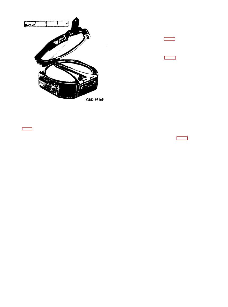
Leather carrying case M19 (fig. 1) is the
the upper end projects slightly above the
only piece of equipment issued with the
body of the compass to engage the cover
compass M2. The case consists of a three-
when it is closed, thereby automatically
piece assembly into which the compass
lifting the needle from its pivot and hold-
fits and has a flap or cover which is an
ing it firmly against the glass window.
integral part of the back piece. This bends
d. Azimuth Scale Adjuster Assembly
over the case and is fastened to the front
and Azimuth Scale. The azimuth scale ad-
juster assembly rotates the azimuth scale
with a snap button. The loop of the carry-
ing case is riveted to the back side of the
to introduce the declination constant. Two
case (not shown in the illustration
teeth of the adjuster engage teeth on the
indicated).
under side of the azimuth scale, so that


 Previous Page
