
TM 32-5865-010-24&P
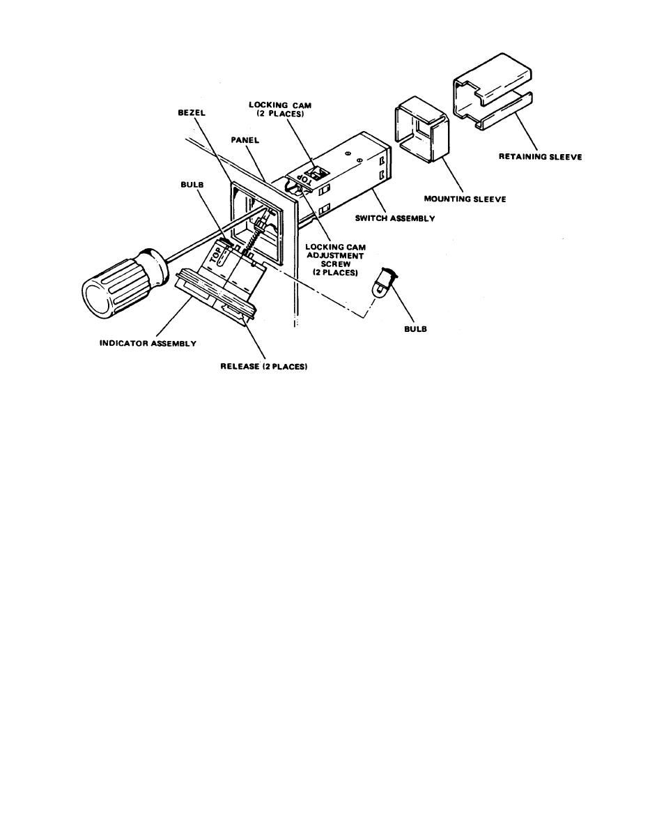
Switch/Indicator Assembly
loosen the two locking cam adjustment
( 6 ) Using a screwdriver,
screws on the replacement switch until two locking cams are
free.
(7) Remove the mounting and retaining sleeve from replacement
switch assembly.
(8) Slide the replacement switch assembly into the front panel,
and replace the mounting and retaining sleeves on switch
assembly from the rear of the front panel.
(9) Using contact insertion tool MS-27534-20 (MK-1961/G),
insert each wiring pin into corresponding terminals on the
replacement switch assembly.
(10) Slide the mounting sleeve up to the rear of front panel,
and slide the retaining sleeve against' the mounting sleeve.
(11) Using a screwdriver, tighten two locking cam adjustment
s crews.
(12) Install two bulbs in the indicator portion of the assembly.
(13) Verify the TOP label on the indicator portion is facing up;
aline the indicator portion with the switch portion and
push in, to the mechanical stop.


 Previous Page
