
TM 11-6625-821-45
farad input of the reciever.
that normally is provided by the sense
(3) Indicator circuit. BEARING INDI-
antenna in an aircraft installation.
CATOR DS3 (fig. 5-3) indicates the
signal across resistor R1 in the con-
bearing data that the receiver pro-
verter is used as the sense antenna
duces from the simulated loop and
signal and is applied to SENSE
sense antenna signals supplied by the
ANTENNA connector J10.
test set. The bearing data from the
receiver is connected to the BEAR-
ING INDICATOR through switch
nector J10, the sense antenna signal
is applied to the receiver through
S4D when RECEIVER-CONTROL
Antenna
SM-446/
Simulator,
switch S4 is in the RECEIVER posi-
ARM93 (sense antenna adapter).
tion.
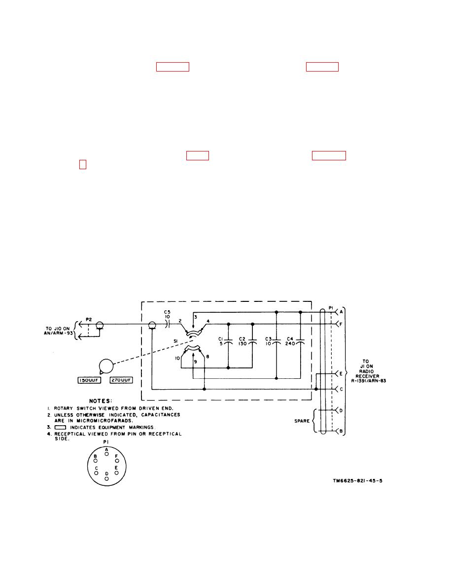
The sense antenna adapter (fig. 1-
nal 27.5-volt dc power source is con-
matching network consisting of ca-
nected to connector J7 in the test set.
pacitors C1 through C5 and switch
Fuse F1 provides 3-ampere protection
S1. When switch S1 is in the 150
for the 27.5 volts dc, and DC POWER
UUF position, capacitor C5 com-
switch S1 removes and applies this
bines with capacitors C1 and C2 to
voltage to the power circuit. When
provide attenuation and impedance
switch S1 is set to ON, 27.5 volts dc
is applied to DC indicator DS1
matching for the 150-micromicro-
farad (uuf) input of the receiver.
through current-limiting resistor R7,
When switch S1 is in the 270 UUF
and lights the DC indicator. Switch
position, capacitor C5 combines
S1 applies the 27.5 volts dc to the re-
with capacitors C3 and C4 to pro-
ceiver through switches S4C in the
test set, S302B in the control unit, and
vide attenuation and impedance
matching for the 270-micromicro-
S4D in the test set. The 27.5 volts


 Previous Page
