
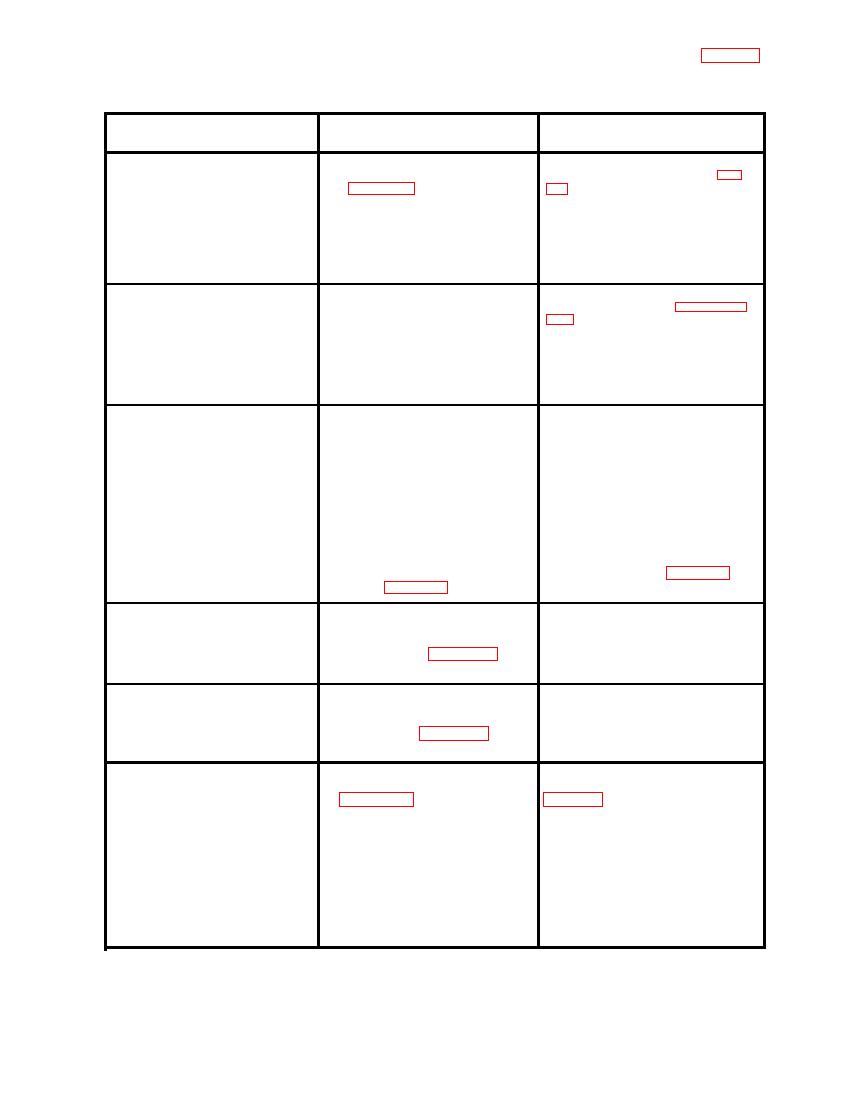
TABLE 6-1. TROUBLESHOOTING CHART (cont)
Remedy
Trouble
Probable Cause
Perfornm ∆270 circuit test of table
Faulty ∆270 polarity switch 1S5
With Turntable at 0 and HEADING
(1, figure 9-12).
7-3, step 2.
SELECTOR at 90, synchro head-
ing does not change when ∆270 is
Faulty ∆270MINUTES switch
set in.
1AT7 (3).
Replace switch.
Faulty HEADING SELECTOR
switch 1AT1 ( 34).
When determining ∆270, elec-
Recalibrate. Refer to paragraphs
E1 is not properly calibrated.
trical swing error minus cor-
procedure.
rected manual error at 90 degrees
does not equal electrical swing
error minus corrected manual
error at 270 degrees within
9 minutes.
Check aircraft transmitter wiring.
With transmitter in aircraft,
Crossed, shorted, or open leads
in aircraft transmitter wiring.
compass headings do not follow
HEADING SELECTOR headings.
Check for faulty wiring in adapter
Crossed, shorted, or open leads
box, adapter cable, and cable W2.
in adapter cable, adapter box or
cable W2.
Aircraft compass system not
Check aircraft compass system:
refer tc applicable aircraft
operating properly.
maintenance manual.
Perform power test of table 7-2,
Faulty MODE SELECTOR switch
1S8 (15, figure 9-12).
step 1, part III.
With transmitter in aircraft, a
Faulty resistor in E 1 voltage
Replace resistor.
large heading error is observed
section of HEADING SELECTOR
on two headings. All other
switch 1AT1 (34, figure 9-12).
headings are normal.
With transmitter in aircraft, a
Faulty resistor in E2 voltage
Replace resistor.
large heading error is observed
section of HEADING SELECTOR
on four headings. All other
switch 1S8 (15, figure 9-12).
headings are normal.
Faulty ∆270 polarity switch 1S5
Perform ∆270 circuit test of
During an electrical-manual
swing operational check, an index (1, figure 9-12).
table 7-3, step 2.
error is observed with a maximum
Faulty ∆270MINUTES switch
error at 90 and 270 degrees.
1AT7 (3).
Faulty ∆270section of HEADING
Replace switch.
SELECTOR switch 1AT1 (34).
Monitor magnetized.
6-5


 Previous Page
